
Starting from January 2025, we have fully transitioned to using the GAZDA G105 thermostat, which stands out for its simplicity and ease of operation. The new model allows the connection of an external room thermostat, making heating control even more convenient.
Unlike the previous TP-16 model, where users sometimes accidentally switched modes (e.g., from heating to cooling), causing difficulties, the GAZDA G105 is designed for maximum simplicity. The device operates exclusively in heating mode, eliminating the possibility of errors and ensuring stable operation of the heating system.
Below are the updated connection diagrams for the KE and BE and R series boilers.
.jpg)
.jpg)
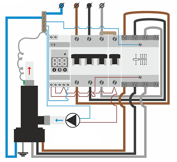
These diagrams show the wiring of GAZDA KE series single-phase electrode boilers with a capacity of 1-4 kW (first diagram) and 5-8 kW (second diagram). Both configurations use the G-105 thermostat for temperature control and an energy monitor, which not only measures power consumption but also displays current, power, voltage, and other system parameters.
🔹 First diagram (1-4 kW) – suitable for small spaces, private homes, or cottages with a 230V single-phase power supply.
🔹 Second diagram (5-8 kW) – also designed for a 230V single-phase power supply but includes a contactor that supports a higher load compared to the first diagram.
Both systems feature a circulation pump to ensure even heat distribution throughout the heating system. Thanks to their compact design and ease of installation, these boilers are an excellent choice for autonomous heating.

This diagram shows the connection of a GAZDA BE series three-phase boiler using the GAZDA G105 thermostat. It illustrates the main system components, including the electrical connections, the 400V network, and the circulation pump.
The GAZDA G105 thermostat ensures simple and convenient operation, with support for connecting an external room thermostat for more precise temperature control.

This diagram illustrates the connection of a GAZDA R series three-phase boiler using the GAZDA G105 thermostat. Similar to the diagram below, which features the TP-16 thermostat, all key components of the system are represented here as well.
The main difference lies in the fact that the GAZDA G105 offers simpler and more convenient control thanks to its built-in support for connecting an external room thermostat. The plastic housing of the R series boilers eliminates the need for grounding, enhancing electrical safety.
From July 2022, we are equipping all control panels for single-phase and three-phase boilers (Galan and GAZDA) with electricity meters.
In addition to kilowatts consumed, it also displays amperes and volts for each phase, cosφ, etc. All wiring diagrams apply to both Galan and Gazda boilers. The only difference is that single-phase Gazda boilers do not have an earthing terminal, as these boilers are covered with dielectric polymer material and do not need earthing.
.jpg)
.jpg)
This is a simple wiring diagram for single-phase boilers up to 4 kW.
For single-phase boilers of 5 and 6 or 8 kW. It differs from the previous scheme with another (more powerful, up to 63A) magnetic contactor and another main switch (from 25A to 40A).
.jpg)
This is a simple wiring diagram for single-phase GAZDA boilers up to 4 kW.


For single-phase GAZDA boilers of 6 or 8 kW. It differs from the previous scheme with another (more powerful, up to 63A) magnetic contactor and another main switch (from 25A to 40A).

It is the scheme shows how to connect follow-up a temperature regulator air to the existing control unit with a temperature regulator on water. For an example it is represented Computherm q7, but it is possible to use any air temperature regulator.


1-External control device (room thermostat, Wi-Fi relay with potential-free contacts, etc.).
2-Circulation pump
3-Power supply lines
1-External control device (room thermostat, Wi-Fi relay with potential-free contacts, etc.).
2-Circulation pump
3-Control box (overcurrent circuit breaker, meter indicating
current, voltage and current power consumption)
These two wiring diagrams of GAZDA single-phase monoblock boilers GM series. The difference in the two circuits is that the second circuit is supplemented with an electricity meter (in addition to the readings of the energy consumed, there is a possibility of displaying the current and voltage)

Wiring diagram for three-phase boilers such as Geyser 4.5, Geyser 6, Geyser 9, Geyser 12, Geyser 15, Geyser 18 and Volcano 25

Exactly the same wiring diagram as shown above, but with the option of connecting an air thermostat

Wiring diagram with WI-FI thermostat. In this example the regulator model KL-WF96D (KONLEN)
We are pleased to introduce the updated Konlen thermostat, produced since January 2024, designed to provide even more precise control over your heating.

This diagram represents the connection of the Wi-Fi thermostat Konlen for a single-phase Galan electrode boiler with a power of up to 3 kW. The thermostat controls the boiler's switching on and off based on the temperature sensor's readings of the heat carrier.
The Konlen thermostat controls the power supply to the boiler by sending a current to the coil of the magnetic contactor through a physical connection. The operating parameters of the thermostat can be remotely configured via Wi-Fi using a mobile application.
The contactor, shown on the right side of the diagram, is designed for a maximum current of up to 20 A, which corresponds to the load of single-phase Galan boilers with a power of up to 3 kW. The regulation and control of the thermostat are carried out through a mobile application, allowing the user to set the required temperature and monitor the system's operation.
The boiler's connection to the thermostat is carried out according to the electrical diagram, ensuring the correct functioning of the heating system.

This diagram represents the connection of the Wi-Fi thermostat Konlen for a single-phase Galan electrode boiler with a power of up to 6 kW. The thermostat controls the boiler's operation by activating or deactivating based on the readings from the temperature sensor of the heat carrier.
The Konlen thermostat regulates the boiler's power supply by sending a current to the coil of the magnetic contactor through a physical connection. The operating parameters of the thermostat can be adjusted remotely via Wi-Fi using a mobile application.
The contactor, shown on the right side of the diagram, is designed for a maximum current of up to 40 A, accommodating the load of single-phase Galan boilers with a power of up to 6 kW.
The regulation and control of the thermostat are conducted through a mobile application, which allows the user to set the desired temperature and monitor the system's operation.
The boiler is connected to the thermostat following the electrical diagram, ensuring the correct functioning of the heating system.

This diagram outlines the setup for connecting the Wi-Fi thermostat Konlen to a three-phase Galan electrode boiler with a capacity of up to 25 kW. The thermostat manages the boiler's functionality, toggling it on or off based on the heat carrier's temperature sensor readings.
The Konlen thermostat controls the boiler's power supply by directing a current to the coil of a 63 A magnetic contactor via a physical connection. Users can remotely fine-tune the thermostat's settings through a Wi-Fi-enabled mobile application, allowing for precise temperature adjustments and system monitoring.

This electrical wiring diagram outlines the setup for connecting single-phase Gazda boilers, suitable for both 2kW and 4kW models. The system is powered through the main circuit breaker, with a 1A circuit breaker placed adjacent to it, designated for the Konlen Wi-Fi thermostat and the circulation pump. Further right, a standard 20A double-pole magnetic contactor is used, capable of handling connections for up to 4kW Gazda boilers. The wiring from the circuit breaker leads to an ammeter, doubling as an electricity consumption meter, which displays current, power, and real-time energy consumption. This phase then moves to the contactor, under the direct control of the Konlen Wi-Fi thermostat. Using a DS18B20 temperature sensor, the Konlen Wi-Fi thermostat regulates the heating medium's temperature by adjusting the electrical phase supplied to the contactor’s coil, with the entire system manageable via Wi-Fi by the user.

This electrical wiring diagram is designed for the installation of single-phase Gazda boilers, suitable for up to 8kW models. The system draws power from the main circuit breaker, beside which a 1A circuit breaker is installed, specifically for the Konlen Wi-Fi thermostat and the circulation pump. To the right of the 1A circuit breaker, a 40A double-pole magnetic contactor is utilized, adequately equipped to connect Gazda boilers of up to 8kW. The electrical phase from this circuit breaker is directed to an ammeter, which also serves as an electricity meter, showcasing current, power, and real-time energy usage. Following this, the phase leads to the contactor, directly controlled by the Konlen Wi-Fi thermostat. The thermostat uses a DS18B20 temperature sensor to monitor and regulate the temperature of the heating medium by appropriately adjusting the electrical phase delivered to the contactor's coil. The entire setup is user-manageable via Wi-Fi, ensuring precise temperature control.

This diagram illustrates the connection of three-phase GAZDA series R electric boilers. The diagram is also applicable to other three-phase GAZDA and Galan boilers, with the difference that the grounding wire is not shown here. This is because GAZDA series R boilers have a fully plastic-coated housing, and therefore do not require grounding. The main components of the diagram are:
-
Thermostat TP-16
-
Electricity meter with ammeter and voltmeter functions
-
Contactor
-
Three-pole circuit breaker
-
Single-pole circuit breaker
The diagram shows the connection to a three-phase 400V network (L1, L2, L3) and neutral (N). The boiler is connected through a contactor and circuit breakers, providing protection and control. The TP-16 thermostat is used to monitor the temperature and control the boiler’s operation.
The absence of the need for grounding in GAZDA series R boilers is an important feature due to their plastic housing, which enhances the electrical safety of the device.

This is a simple wiring diagram for single-phase boilers up to 3 kW.

For single-phase boilers of 5 and 6 kW. It differs from the previous scheme with another (more powerful, up to 40A) magnetic contactor and another main switch (from 25A to 32A).
It is the classical scheme of connection of three-phase electrode boilers. Such as Geyser 9, Geyser 15, and Vulcan 25.


It is the scheme shows how to connect follow-up a temperature regulator air to the existing control unit with a temperature regulator on water. For an example it is represented Computherm q7, but it is possible to use any air temperature regulator.

This scheme shows how to connect three phase boiler (for example the Geyser 9 or Geyser 6) to uniphase electric network. It is useful in case you have only 230 V, and the heated area at you is more than 250 m3
Distinctiveness of this scheme is that instead of a one triple-pole automatic breaker we establish three onepolar. Thereby there is an opportunity to operate a boiler three steps of heating.
For example: the Geyser 6 - three levels on 2 kW each level. And the Geyser 9 - three levels on 3 kW each level.


This connection diagram for three-phase boilers with ammeter addition.
This connection diagram for three-phase boilers with addition of ammeter and air thermo regulator.

In this diagram, we show you how to connect a third-party relay wi-fi to the control box.

This scheme for connecting the boiler Vulcan 36

This scheme for connecting the boiler Vulcan 50